|
|
|
Current -
Make your choice.
|
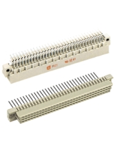
Types har-bus® 64, har-bus® 64 invers
Number of contacts: 160
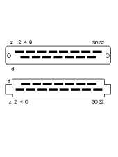
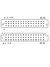
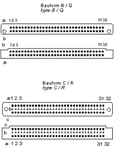
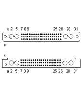
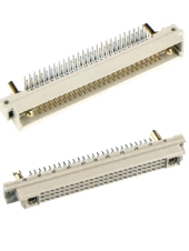
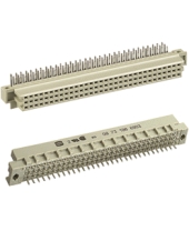
Types B, C and M, inverse Types Q and R
Number of contacts: 96, 64, 32, 16, 78+2, 60+4, 42+6, 24+8
Clearance/Creepage 1.2/1.2 mm min.
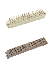
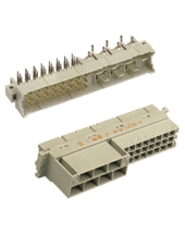
Type MH
Number of contacts: 24+7
Clearance/Creepage 4.5/8.0 (1.6/3.0) mm min.

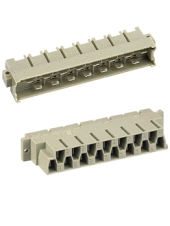
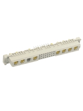
Types D, E and F
Number of contacts: 48, 45, 32, 24
Clearance/Creepage 3.0 (1.6) / 3.0 mm min.

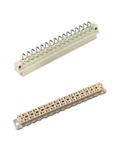
Type H
Number of contacts: 15
Clearance/Creepage 4.5/8.0 mm min.
|
Number of contacts -
Make your choice.
|
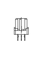
Type H
For faston 6,3 x 2,5 or with solder pins.
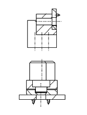
Type H
For faston 6,3 x 2,5 or with solder pins.


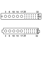
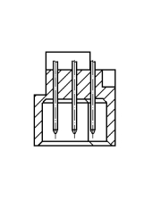
Type MH.
Order separately high current, high voltage, coaxial and
fibre optic contacts.

Type M.
Order separately high current, high voltage, coaxial and
fibre optic contacts.

Type M.
Order separately high current, high voltage, coaxial and
fibre optic contacts.
Type M.
Order separately high current, high voltage, coaxial and
fibre optic contacts.

Type M.
Order separately high current, high voltage, coaxial and
fibre optic contacts.
|
Row pitch face -
Make your choice.
|
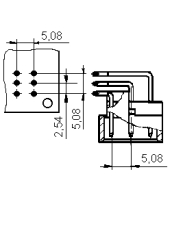
Contact spacing 2.54 mm

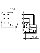
Contact spacing 5,08 mm
|
|
|
Number of contacts: 64, 32, 20, 16
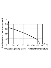
Working current 2 A max.
Clearance/creepage 1.2/1.2 mm min.
Number of contacts: 96, 64, 48, 32, 30, 20, 16
Working current 2 A max.
Clearance/Creepage 1.2/1.2 mm min.
Number of contacts: 32
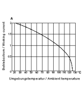
Working current 6 A max.
Clearance/Creepage 3.0/3.0 mm min.
Number of contacts: 48
Working current 6 A max.
Clearance/Creepage 3.0(1.6)/3.0 mm min.

Number of contacts: 48, 45, 32
Working current 6 A max.
Clearance/Creepage 1.6/3.0 mm min.
Number of contacts: 15, 14+1, 13+2
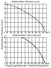
Working current 15 A max.
Clearance/Creepage 4.5/8.0 mm min.
Number of contacts: 3
Working current 15 A max.
Clearance/Creepage 4.5/8.0 mm min.
Number of contacts: 78+2, 60+4, 42+6, 24+8
Working current 2 A max.
Clearance/Creepage 1.2/1.2 mm min.
Number of contacts: 78+2, 60+4, 42+6, 24+8
Working current 2 A max.
Clearance/Creepage 1.2/1.2 mm min.

Number of contacts: 64, 32, 16
Working current 2 A max.
Clearance/creepage 1.2/1.2 mm min.
Number of contacts: 160, 96, 64, 48, 32, 16
Working current 2 A max.
Clearance/Creepage 1.2/1.2 mm min.

Number of contacts: 96, 64
Working current 2 A max.
Clearance/Creepage 1.2/1.2 mm min.

Five rows, 160 poles
additional contacts for I/O and system upgrade
data transfer rates up to 320 MByte/s
|
Termination -
Make your choice.
|
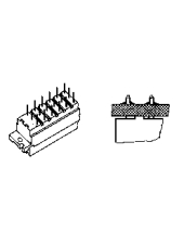
Solder pins for printed circuit boards
Surface Mount Compatible (SMC)
Solder pins for reflow soldering
Press-in technique for P.C. boards
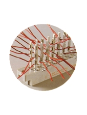
Wrap posts for automatic wiring techniques
|
Termination length -
Make your choice.
|

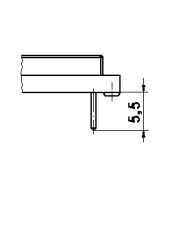
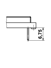
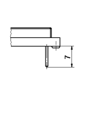
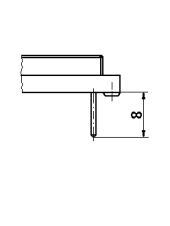
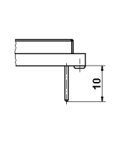
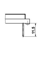
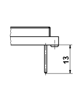
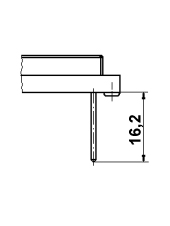
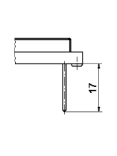
Straight solder pins
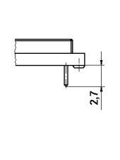
Straight solder pins
Straight solder pins
Straight or angled solder pins /
angled press-in termination

Straight solder pins
Straight solder pins

Straight solder pins
Straight solder pins
Straight solder pins

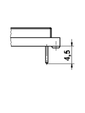
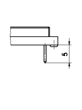
Straight press-in termination.
4.5 mm press-in pins for contacts in row a, b and c.
5.0 mm press-in pins for contacts in row z and d.
Straight press-in termination

Straight press-in termination
Straight press-in termination
Straight solder pins
Open solder lugs
Straight solder pins
Straight press-in termination
Possible quantity of wraps per wire wrap post depends on the diameter of the wire.
0.25 mm² : 6 wraps / 0.5 mm² : 4 wraps (IEC 60352-1)

Possible quantity of wraps per wire wrap post depends on the diameter of the wire.
0.25 mm² : 6 wraps / 0.5 mm² : 4 wraps (IEC 60352-1)
|
Performance Class -
Make your choice.
|

as per IEC 60603-13
400 mating cycles, 4 days gas test using 10 ppm SO2.
Measurement of contact resistance, then visual inspection.
50 mating cycles, no gas test. Then visual inspection.
|
Clearance/Creepage -
Make your choice.
|
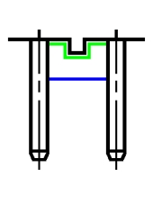
Working current 2 A max.
Green: Creepage. Blue: Clearance.
Working current 6 A max.
Green: Creepage. Blue: Clearance.
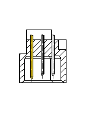
Working current 6 A max. + 15 A max.
Green: Creepage. Blue: Clearance.
Working current 6 A max.
Green: Creepage. Blue: Clearance.
Working current 15 A max.
Green: Creepage. Blue: Clearance.
|
Board fixing -
Make your choice.
|

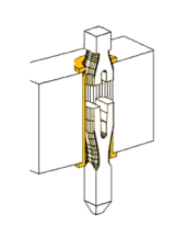
Tin plated snap-in-clip; mounting force 40-60 N;
Provides transport safety before soldering 15 N
Before and during soldering, teh connectors are fixed onto the pcb with fou kinked contacts
|
First mating contact -
Make your choice.
|
without first mating contacts.
|
Terminal finish -
Make your choice.
|
Surface hard-silver plated.
Surface hard-gold plated.
Termination selectively gold plated
similar to the performance level of the contact zone.
For interfacing using types B, C, Q and R
wrap posts have to be selectively gold plated.
solderable
|
Railway Classification -
Make your choice.
|
|
Fixing flange -
Make your choice.
|
|
Version -
Make your choice.
|
|
Contact gender -
Make your choice.
|
|
Coding facility -
Make your choice.
|
|
Type or rear connector -
Automatically selected due to your choice.
|
|
|