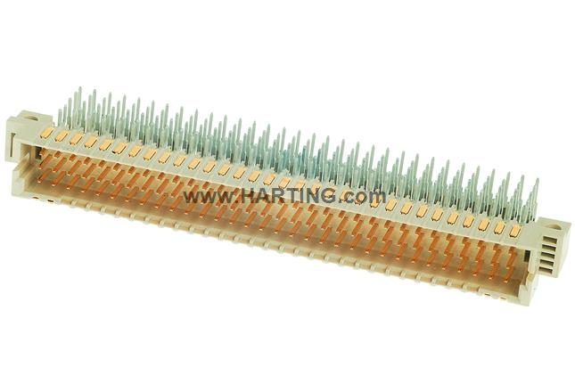
Properties Overview
Male connector
Reflow soldering termination (THR), Wave soldering termination
Rated current: 1 A
Contacts: 160
Angled
Copper alloy
Noble metal over Ni Mating side, Sn over Ni Termination side
Performance level: 1, acc. to IEC 61076-4-113
PCB fixing: With fixing flange
Liquid crystal polymer (LCP)
Beige
Product Details
Identification
- Category Connectors
- Series har-bus® 64
- Element Male connector
- Description of the contact Angled
Version
-
Termination method
Reflow soldering termination (THR)Wave soldering termination
-
Connection type
Motherboard to daughtercardExtender card
- Number of contacts 160
- Contact configuration Rows z, a, b, c, and d, positions 1, 2, ... , 31, 32
-
Leading contact on position
d1d2d31d32
- PCB fixing With fixing flange
Technical characteristics
- Contact rows 5
- Contact spacing (termination side) 2.54 mm
- Contact spacing (mating side) 2.54 mm
- Rated current 1 A
- Rated current Rated current measured at 20 °C, see derating curve for details
-
Clearance distance
1.2 mm between 2 rows (a, b, c)1.2 mm between 2 rows (z, d)1.2 mm between 2 contacts in a row (a, b, c)1 mm between 2 contacts in a row (z, d)
-
Creepage distance
1.2 mm between 2 rows (a, b, c)1.2 mm between 2 rows (z, d)1.2 mm between 2 contacts in a row (a, b, c)1 mm between 2 contacts in a row (z, d)
- Insulation resistance >1010 Ω
-
Contact resistance
≤20 mΩ for rows a, b, c≤30 mΩ for rows z, d
- Limiting temperature -55 ... +125 °C (during reflow soldering max. +240 °C for 20 s)
- Insertion force ≤ 160 N
- Withdrawal force ≤ 120 N
-
Performance level
1acc. to IEC 61076-4-113
- Mating cycles ≥ 500
- Test voltage Ur.m.s. 1 kV
- Isolation group IIIa (175 ≤ CTI < 400)
- Hot plugging No
Material properties
- Material (insert) Liquid crystal polymer (LCP)
- Colour (insert) Beige
- Material (contacts) Copper alloy
-
Surface (contacts)
Noble metal over Ni Mating sideSn over Ni Termination side
- Material flammability class acc. to UL 94 V-0
- RoHS compliant
- ELV status compliant
- China RoHS e
- REACH Annex XVII substances Not contained
- REACH ANNEX XIV substances Not contained
- REACH SVHC substances Not contained
- California Proposition 65 substances Yes
-
California Proposition 65 substances
LeadNickel
Specifications and approvals
Commercial data
- Packaging size 5
- Net weight 25 g
- Country of origin Germany
- European customs tariff number 85366990
- GTIN 5713140000025
- ETIM EC002637
- eCl@ss 27460201 PCB connector (board connector)
Downloads
Download Package
Knowledge
0
Compare


